DAZA/DNWA

Stages
-
To get started with your stock RS3/TTRS, our first suggestion is always a vehicle interface solution called DS1. It enables not only seamless ECU flashing for a tuner and end user alike, but also includes heaps of advanced features, including enabling custom functions and custom code to be written to the ECU.
In addition to the DS1, we also recommend a flexfuel sensor kit which integrates nicely with the DS1 and enables you to run any fuel blend without having to reflash maps or concern yourself with mixing a preciese ethanol blend.Ask your doctor if CustomTuning is right for you. Member FDIC.
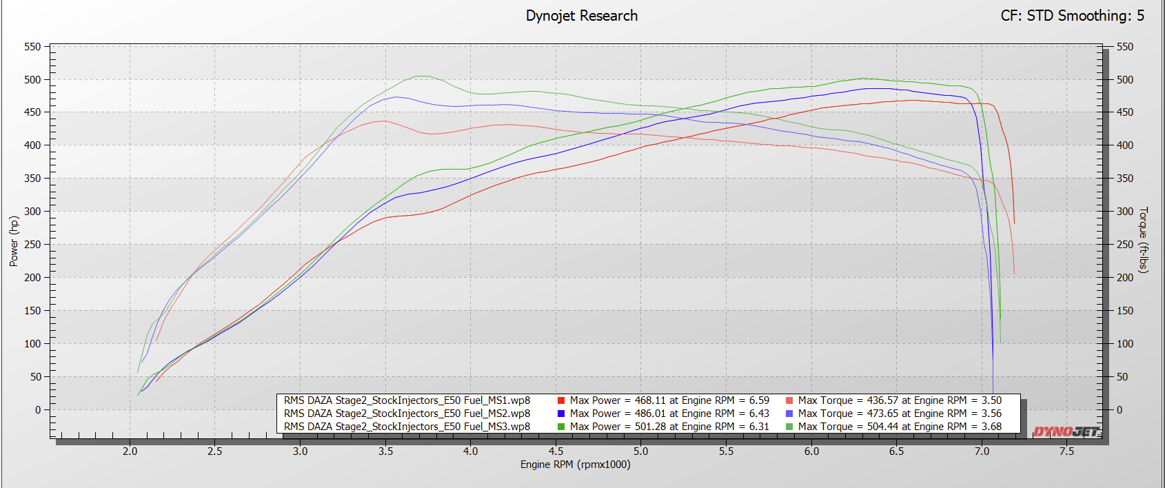
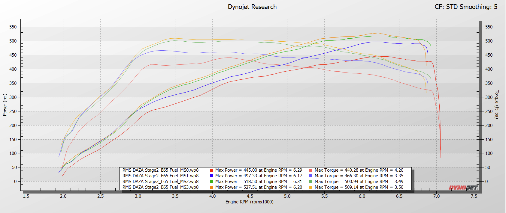
-
Upgraded Port Fuel Injectors
Hi-Flow Downpipe
Hi Flow Air Intake
Upgraded Intercooler
-
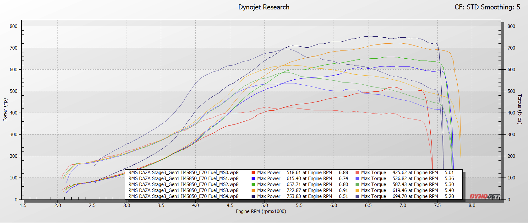
Stage 2 Hardware, plus:
Upgraded Hybrid Turbocharger
DSG Catch Can
Engine PCV Catch Can
Upgraded LPFP System
(This can surpass the strength limits of the factory connecting rods, so output will be limited to apx 650whp/500wtq)
-
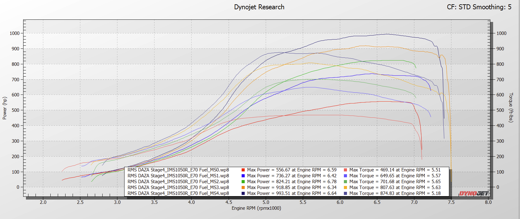
Stage 3 Hardware, plus:
“Full Frame” turbo upgrade (IMS850+)
DQ500 Clutch Upgrade
Minimum upgrade of engine internals includes connecting rods, pistons, valve springs.
*Minimum upgrade of engine internals includes connecting rods, pistons, valve springs
-
This Stage features a comprehensive powertrain upgrade package that is happy living at 1200whp.
Additional hardware required:
Sleeved Engine Block
Upgraded Valves
Further upgraded LPFP system.


The RMS Difference/The RMS Advantage
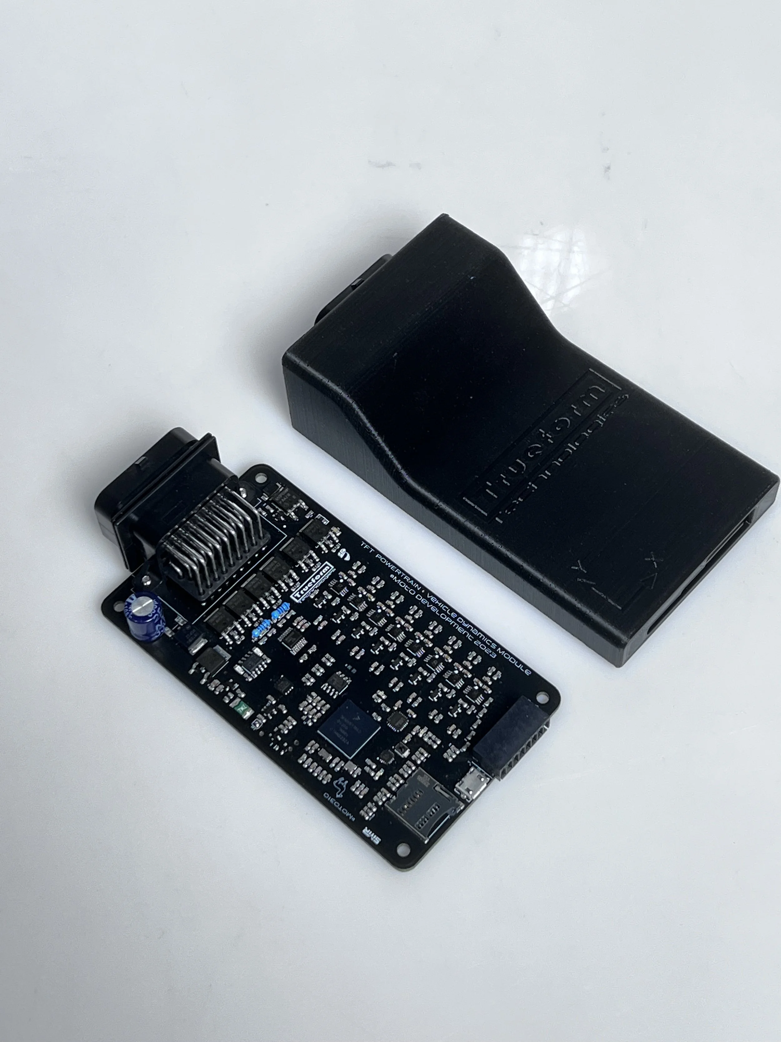
Expanding and Enhancing the OEM ECU to deliver unparalleled features and performance.

Advanced OEM ECU Features, enabled by TFT Module
-
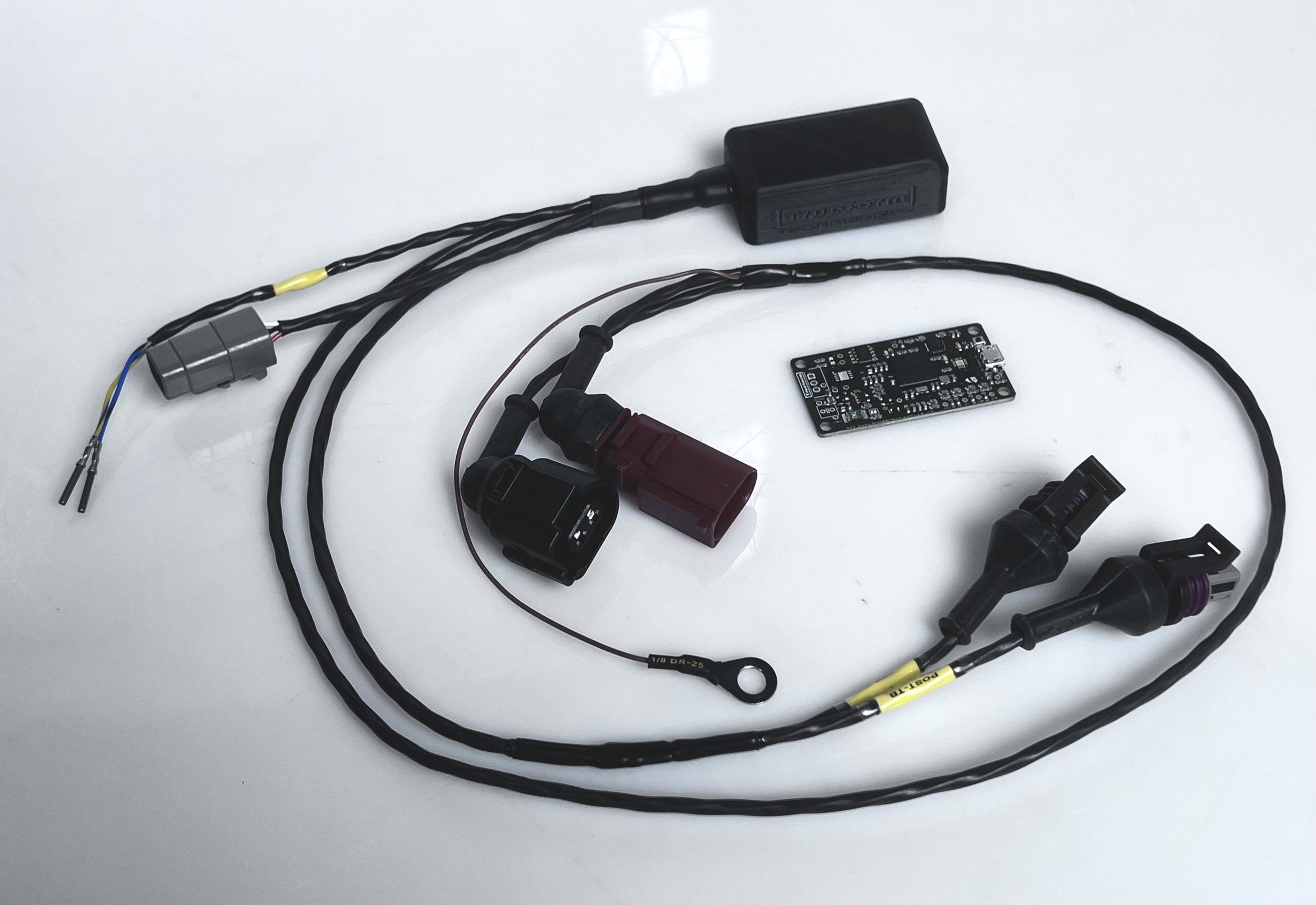
The TFT KitchenSink Module has the following sensor signal inputs:
(5) 0-5v Analog Inputs, Conditioned for common analog 0-5v sensors.
(1) 0-14.5v Analog Input, Conditioned for general analog signals or activation circuits.
(2) 0-5v Analog/Dig/Freq Inputs, Unconditioned. Can be used for general Analog DC signals, or Square Wave inputs such as Turbo Speed Signals. Data outputs for each input include Analog Voltage, PWM DC, Period, and Frequency (simultaneously)
(2) 0-5v Dig/Freq Inputs, Unconditioned. Can be used for general Analog DC signals, or Square Wave inputs such as Turbo Speed Signals. (Both Raw and Calculated RPM is output (calculated data is based on a standard Garrett Sensor and 7x7 compressor wheel)
(2) 0-14.5v Dig/Freq Inputs, Unconditioned. Can be used for high speed 12v activation circuits. Data outputs for each input include PWM Duty Cycle, Period and Frequency (simultaneously)
(1) VR Sensor Input (+ and -).
(8) Temperature Sensor Inputs. All 8 can be K-Type Thermocouples, or Temp7 & 8 can be substituted for NTC thermistors (via solder bridge on board)
The TFT BasicDAZA Module has the following sensor signal inputs:
(3) 0-5v Unipolar Inputs, Conditioned for common analog 0-5v sensors.
(1) 0-14.5v Unipolar Input, Conditioned for general analog signals or activation circuits.
(1) 0-5v Unipolar Input, Unconditioned for Digital/Freq 0-5v Square Wave inputs such as Turbo Speed Signal. (Both Raw and Calculated RPM is output (calculated data is based on a standard Garrett Sensor and 7x7 compressor wheel)
Analog Signals output to CAN is (voltage * 1000) as a 16bit unsigned integer, little endian. For example, a value of 3152 seen in CANextX via DS1/DS2 will mean the signal voltage input is 3.152v.
-
The KitchenSink module is equipped with (4) Standard LowSide MOSFETs, (2) Gate-driven LowSide MOSFETs, and (1) HighSide MOSFET. The BasicDAZA module is equipped with (1) Standard LowSide MOSFET.
These can be activated/controlled either by CAN messages created/transmitted by custom DS1 frames, by sensors and activation windows managed by the TFT Module, by PT_CAN Data passively collected by the TFT Module, or by active Service22 sessions initiated by the TFT Module. In other words, the outputs can be activated and managed by any type of signal or configuration.
Typical outputs can include:
- Bypass Valve momentary/timed actuation (Default configuration for LS1)
- Wastegate/MAC Valve Activation , which is far superior to MED17’s range of control over MAC valve. (Default configuration for LS5)
- PWM Trigger of SecondaryLPFP for smooth pump activation/pressure increase (best if used with solid state relay)(Default configuration for LS3)
- CO2 Solenoid trigger for automatic parachute deployment (Default configuration for HS1, see TFT Configuration Manual)- Methanol Pump Activation
- Methanol FAV Solenoid Control (Precise flow control with pump pressure constant at 200psi)
- Nitrous Purge and Primary Solenoids (15A Max Continuous)
- Additional MAC Valves/ Control Solenoids/Electric BOVs
- Nitrous Bottle Heater Control (Bottle Pressure can be PID Controlled via TFT Module)Default Configuration of LowSide MOSFET 1,2,3,4 (LS1, LS2, LS3, LS4):
Current Limit of 25amps momentary, 15amps continuous.
These are controlled/activated by one of 3 user-selectable operating modes, with user-adjustable PWM Frequency.Mode 1: LS1 Output to activate with a static internal timer which is triggered by a value > 0 at 0x743 bytes 0-1. This can be used to activate BPVs with a preset activation time, without relying on inconsistent TCU/Gearshift status data or the ECU's CAN task manager for precise timing. Preset timer configurable in the next config mode.
Mode 2: LS1 Output to use full range of PWM DC. This can be used to control EBCS, and the frequency can be adjusted in the next config mode. (For example, sending a raw int value of 1,637 to bytes 0-1 at 0x734, the TFT Module will operate LS1 at 16.37% duty cycle).
Mode 3: Hybrid/Combined Operation.
When sending raw 16bit little endian value of 1 to 1000 to 0x743, the Activation Timer (in ms) will equal the value received in 0x743. For example, sending a value of 275 will result in an activation duration of 275ms.
When sending raw 16bit little endian value of 1001 to 10,000, it will operate in PWM DC, with DC = value * 0.01. (For example, sending a raw value of 1650 to 0x743, the TFT Module will operate LS1 at 16.5% duty cycle). The PWM Frequency can be adjusted in the following config option.User-Selectable/Adjustable Configurations performed via CC Stalk/MFSW Inputs, briefly described below:
Job 61-66: Adjust LS1-6 Output Mode Setting (1-3)
Job 71-76: Adjust LS1-6 Output Static Activation Timer (0-100, which equates to 0 to 1000ms)
Job 81,83-86: Adjust LS1/2 and LS3, LS4, LS5, LS6 Output PWM Frequency (0-100). -
Item description
-
Stock LC System (Which is still employed by the common DAZA tuners): Simple 2-step Rev limiter, which uses cylinder suppression to manage engine RPM at the desired setpoint. Once the brake is released, there is no LC based torque strategy employed to manage the clutch engagement, wheel slip, etc. It’s functionally equivalent to N/A car with a 2-step rev limiter, and dumping the clutch hoping for traction. There is no strategy to assist with building boost, so the user must launch at excessively high RPM in order to avoid bogging off the line, which is needlessly harsh on drivetrain components and sacrifices consistency.
Our preferred strategy is simple in concept, and moderately complex behind the curtain… We want to launch the car at the lowest possible engine RPM, so long as we have sufficient airflow for the prescribed launch torque and reserve torque that can be used via dynamic interventions/reductions to manage clutch slip and wheelslip targets throughout the entire launch sequence.
When the vehicle is equipped with a TFT BasicDAZA or KitchenSink Module, sophistication and user adjustable settings are expanded greatly with two stages of engineRPM setpoints controlled by a boost window. which are especially helpful for those with very large turbos. Of course, all of these variables are adjustable on-the-fly with the CC Stalk/Steering Wheel buttons, with the settings being displayed on the Instrument Cluster for easy navigation.
In addition to the torque/ignition management strategy to promote spooling the turbo, along with managing engine RPM for Launch without the 2-step limiter approach, the TFT Module allows for splitting the stationary phase of the launch control into two stages with separate engineRPM targets, controlled by boost window settings (everything is user-adjustable, on the fly via CC Stalk or MFSW). The two stages can be described as 1) “EngineRPM Ramp”, which is generally higher to spool the turbo quicker, and 2) “EngineRPM Hold”, which is used as the engine RPM target to be held once the desired boost level is achieved. The transition between these stages is controlled by a user-adjustable Boost Window, which includes three different boost levels: 1) “Entry Threshold Pressure”, 2) “Minimum Maintain Pressure” and 3) “Max Overboost Pressure”
The following is the typical launch sequence, with example variables:
- ”EngineRPM Ramp” setpoint: 4250rpm
- “EngineRPM Hold” setpoint: 3750rpm
- BoostWindow “Entry Threshold Pressure”: 2800hpa
- BoostWindow “Minimum Maintain Pressure”: 2200hpa
- BoostWindow “Max Overboost Pressure”: 3400hpaWhile stationary, apply the brake pedal and accel pedal to begin Launch.
The engine will be revving up and holding at the “EngineRPM Ramp” of 4250rpm, using a torque/ignition management mode to promote spooling the turbo, not merely a simple 2-step rev limiter.
Once the boost surpasses the “Entry Threshold Pressure”, the engine now transitions to target the “EngineRPM Hold” setpoint of 3750. It will then hold this engineRPM using the same torque management strategy, and only using minimal cylinder suppression/cuts as necessary (almost never). It will maintain this engine RPM until the brake is released (or it is instructed to exit launch mode, transition back to “Ramp” stage, etc)
If the boost pressure drops below the “Minimum Maintain Pressure” of 2200hpa, it will transition back to the “Ramp” RPM setpoint.
If the boost pressure exceeds the “Max Overboost Pressure”, it will suppress single cylinder combustion events until the boost pressure is back within the Min and Max window again.
-
As the KitchenSink module has 3 CAN transceivers communicating on the PT-CAN, Suspension/Instrument Cluster, and OBD CAN networks, it is able to passively sniff, and actively request data from practically all modules in the vehicle. This data dramatically enhances one’s understanding of the vehicle operations, and is very helpful when trying to extract maximum performance out of the powertrain and suspension systems.
The BasicDaza is only on the PT-CAN, therefore it will only communicate, log and perform functions related to the ECU and TCU (and Syvecs AWD Controller, if configured)Typically, the following data is collected, compressed, and transmitted into the ECU for seamless DS2 datalogging. One click of a single .bat file, one CSV file generated, no fumbling around with multiple datalog files, timestamps, etc… Just all the data you want, with minimal buttons to click.
TCU
All Commanded & Actual Temps, Pressures, Torques, etc
Raw Shift Progress/Statuses
Adaptation Statuses/Safety Modes
Launch Control Statuses, Variables (Most come from ECU RAM)
AWD (OEM Haldex)
All Temps
All Pressures (R8/Huracan Only)
Pump Voltage, PWM Signal, Current
Statuses/Safety Modes
AWD (Syvecs AWD Controller, with secondary CAN wired to PT-CAN)
DutyCycle Base & Final
Pump Current
AWD Potentiometer
AWD Pot Multiplier
Anything else you’d like to configure the Syvecs to send
Suspension
Ride Height Sensors
*Raw and Corrected vals processed. (User can reset height offsets on-the-fly via CC Stalk/Multifunction Steering Wheel in the “TFT ControlCenter” , Job 11.
ABS
Dyno Mode Status
(Most other vehicle dynamics vars come from ECU RAM)
-
Using the CC Stalk and/or MultiFunction Steering Wheel, you can perform many OEM Diagnostic and Service functions, including but not limited to:
Clear DTCs (can select only ECU & TCU, or ALL modules)
Perform DQ500 BasicSettings Resets
Activate/De-Activate Dyno Mode
Disable/Enable Longitudinal Controller
Activate Secondary LPFP for Fuel Tank Purge (Depending on Secondary LPFP Config)
Perform Haldex BasicSettings/Adaptations Reset (OEM Haldex Controller)
-
Using the CC Stalk or MultiFunction Steering Wheel, you can configure the TFT Module and the OEM ECU to work symbiotically with your vehicles’s hardware, and perform many functions related to diagnostic systems, internal sensing and data acquisition calibrations/resets, etc. Including, but not limited to:
Configure TFT Module Outputs - Change Mode, Adjust Activation Timers, Adjust PWM Frequency, etc.
Configure TFT Module Temp Inputs 7&8 (K-Type Thermocouple vs 10k NTC Thermistor)
Configure Suspension Level Sensor Input Type (OEM DCC or Hardwired)
Reset "Offset” for Suspension Level Sensors, for datalogging with “calibrated” static ride height
Calibrate Internal IMU
-
Using the CC Stalk or MultiFunction Steering Wheel, you can quickly adjust settings for all of the following:
Boost By Gear
TFT “AutoShift” RPM Setpoints for all WOT upshifts and no-gas downshifts.
Custom Traction Control SlipRate Target and Correction Aggression
Launch Mode EngineRPM Setpoints for Stage 1 and 2 (Ramp and Hold)
Launch Mode Boost Window(s)
Burnout Mode RPM Limiter Setpoint
IMU Calibrations
Set Parachute “Arm” Speed
-
Item description
Expanded OEM ECU Functions and Features
-
-
Simple 2-Step rev limiter that is activated by the Hazard lights (to jive with the 2WD mode activation in Syvecs AWD Controller)
With the ECU Tune only, the target BurnoutMode Engine RPM is adjustable by a repurposing of the “LaunchRPM Override”, wherein the BurnoutMode EngineRPM setpoint = (LaunchRPM Override Setpoint - 1000).
With vehicles equipped with a TFT Module, this is adjustable via the “TFT ControlCenter” in Job 40.
Job 40 - Will display current EngineRPM setting on tachometer; use CC Stalk UP/Down OR MFSW Left Rotary Button Up/Down to increment/decrement RPM setpoint
-
Stock LC System (Which is still employed by the common DAZA tuners): Simple 2-step Rev limiter, which uses cylinder suppression to manage engine RPM at the desired setpoint. Once the brake is released, there is no LC based torque strategy employed to manage the clutch engagement, wheel slip, etc. It’s functionally equivalent to N/A car with a 2-step rev limiter, and dumping the clutch hoping for traction. There is no strategy to assist with building boost, so the user must launch at excessively high RPM in order to avoid bogging off the line, which is needlessly harsh on drivetrain components and sacrifices consistency.
Our preferred strategy is simple in concept, and moderately complex behind the curtain… We want to launch the car at the lowest possible engine RPM, so long as we have sufficient airflow for the prescribed launch torque and reserve torque that can be used via dynamic interventions/reductions to manage clutch slip and wheelslip targets throughout the entire launch sequence.
When the vehicle is equipped with a TFT BasicDAZA or KitchenSink Module, sophistication and user adjustable settings are expanded greatly with two stages of engineRPM setpoints controlled by a boost window. which are especially helpful for those with very large turbos. Of course, all of these variables are adjustable on-the-fly with the CC Stalk/Steering Wheel buttons, with the settings being displayed on the Instrument Cluster for easy navigation.
In addition to the torque/ignition management strategy to promote spooling the turbo, along with managing engine RPM for Launch without the 2-step limiter approach, the TFT Module allows for splitting the stationary phase of the launch control into two stages with separate engineRPM targets, controlled by boost window settings (everything is user-adjustable, on the fly via CC Stalk or MFSW). The two stages can be described as 1) “EngineRPM Ramp”, which is generally higher to spool the turbo quicker, and 2) “EngineRPM Hold”, which is used as the engine RPM target to be held once the desired boost level is achieved. The transition between these stages is controlled by a user-adjustable Boost Window, which includes three different boost levels: 1) “Entry Threshold Pressure”, 2) “Minimum Maintain Pressure” and 3) “Max Overboost Pressure”
The following is the typical launch sequence, with example variables:
- ”EngineRPM Ramp” setpoint: 4250rpm
- “EngineRPM Hold” setpoint: 3750rpm
- BoostWindow “Entry Threshold Pressure”: 2800hpa
- BoostWindow “Minimum Maintain Pressure”: 2200hpa
- BoostWindow “Max Overboost Pressure”: 3400hpaWhile stationary, apply the brake pedal and accel pedal to begin Launch.
The engine will be revving up and holding at the “EngineRPM Ramp” of 4250rpm, using a torque/ignition management mode to promote spooling the turbo, not merely a simple 2-step rev limiter.
Once the boost surpasses the “Entry Threshold Pressure”, the engine now transitions to target the “EngineRPM Hold” setpoint of 3750. It will then hold this engineRPM using the same torque management strategy, and only using minimal cylinder suppression/cuts as necessary (almost never). It will maintain this engine RPM until the brake is released (or it is instructed to exit launch mode, transition back to “Ramp” stage, etc)
If the boost pressure drops below the “Minimum Maintain Pressure” of 2200hpa, it will transition back to the “Ramp” RPM setpoint.
If the boost pressure exceeds the “Max Overboost Pressure”, it will suppress single cylinder combustion events until the boost pressure is back within the Min and Max window again.
-
Utilizing the relatively high-resolution OEM sensors in the MQB platform, we’re able to achieve very high fidelity traction management, with user-adjustable SlipRate Targets and CorrectionAggression to optimize the user experience and performance for any given surface condition.
With the ECU Tune only, there can be 3 different levels of custom traction control, selectable by DriveSelect Settings, which can also be enabled/disabled for individual map slots, with varying levels of aggression, per request. (essentially everything is configurable, per request)
With the TFT Module, the level of controls and adjustment resolution increases to utilize a TargetSlipRate, and 16 levels of CorrectionAggression (user adjustable via CC Stalk and/or MFSW Buttons)
User Adjustables in “TFT Control Center”:
Job 50: Set TractionControl SlipRateTarget (0 -100%)
Job 51: Set TractionControl CorrectionAggression (Level 0-15)
-
-
-
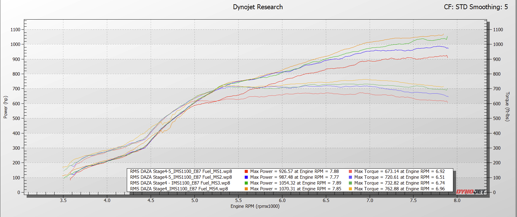
Seemingly uncommon in the DAZA world, we’re actually utilizing the all of the available OEM boost control systems along with custom maps to deliver highly refined, consistent and robust boost control. Say goodbye to squiggly boost/torque curves and curious excuses.
-
Starting with the default Rolling AntiLag system created and deployed by DS1, we’ve simply made necessary ‘fixes’ to allow for stable/unaltered boost targets while RAL is active. If you look at a datalog and see your boost target steadily reduce while you have RAL active, and then slowly recover after you release RAL, you’re being robbed of precious performance. An RMS ECU tune fixes that.